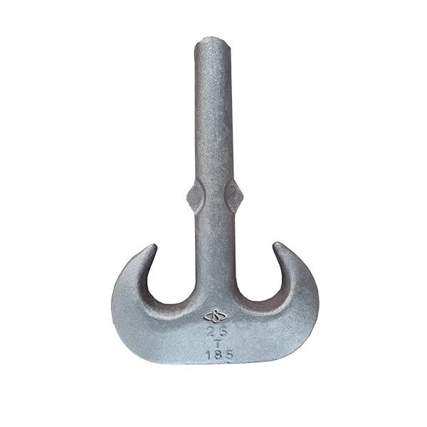
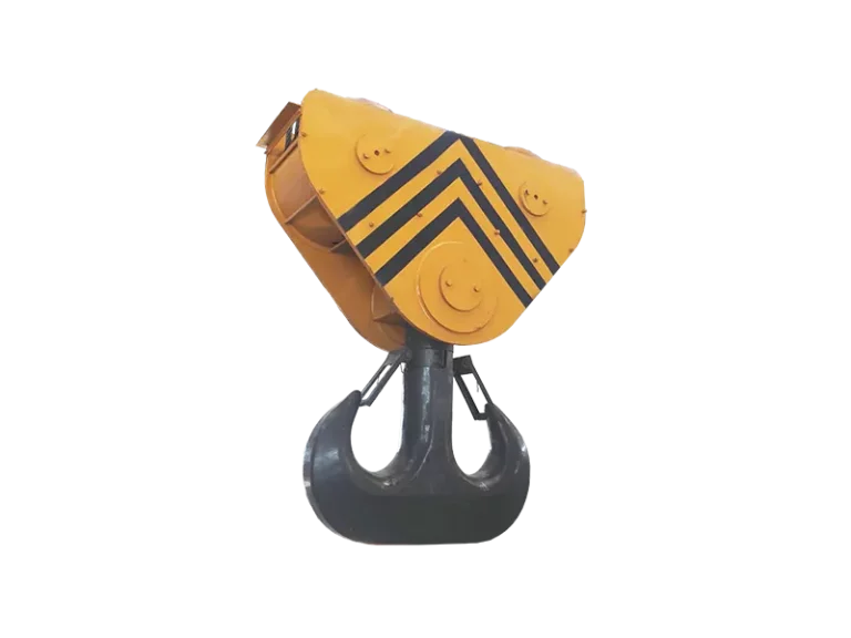
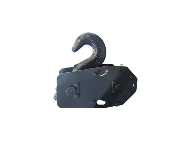
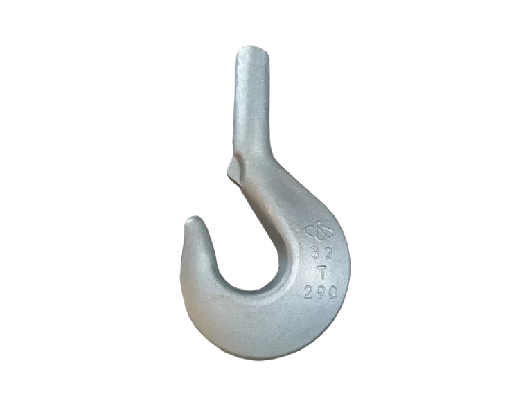
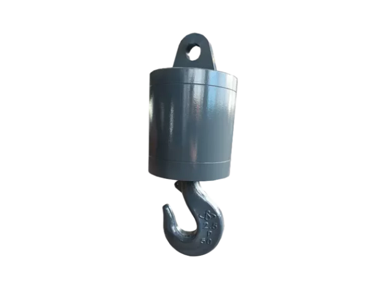
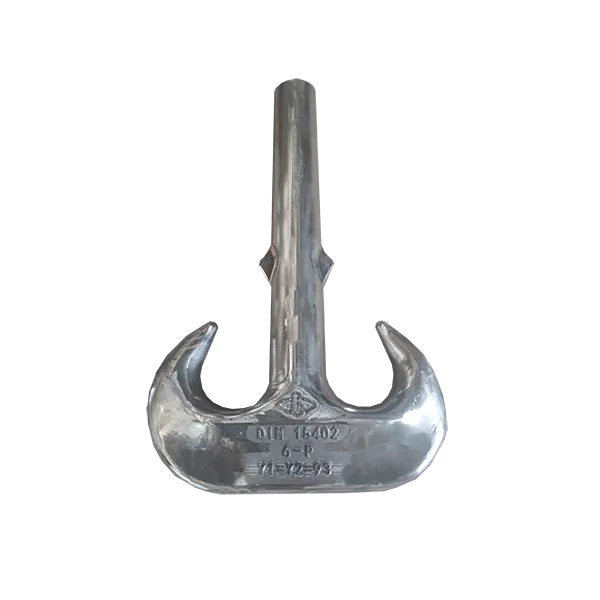
Note: This document is a comprehensive technical reference compiled from publicly available DIN 15401 Part 2 data, manufacturer catalogs and industry sources. DIN standards are copyrighted and available for purchase from Beuth Verlag (www.beuth.de). This reference is intended for technical understanding and quick lookup, not as a substitute for the official standard.
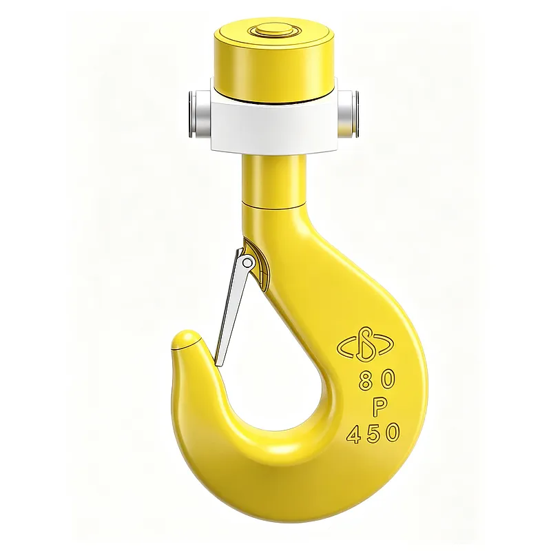
1. Standard Title and Scope
Standard: DIN 15401 Part 2
Full Title (German): Lasthaken für Hebezeuge; Einfachhaken; Fertigteile mit Gewindeschaft
Full Title (English): Lifting hooks for lifting appliances; Single hooks; Finished parts with threaded shank
Scope: DIN 15401 Part 2 specifies the dimensions, materials, machining requirements, proof load testing, marking and inspection of finished forged single hooks with threaded shank for lifting appliances. These hooks are fully machined, threaded, heat-treated, tested and marked, ready for direct assembly into crane hook blocks (hook suspensions) per DIN 15411.
Applicable hook types: Finished single hooks with threaded shank, available in three types based on forging method and nose configuration:
- GSN: Drop forged (S) single hooks, hook Nos. 10 to 40, with threaded shank (G) and with nose (N)
- GF: Hammer forged (F) single hooks, hook Nos. 10 to 250, with threaded shank (G) and without nose
- GFN: Hammer forged (F) single hooks, hook Nos. 10 to 250, with threaded shank (G) and with nose (N)
Relationship to other standards:
- DIN 15400: Lifting hooks — materials, mechanical properties, lifting capacity and stresses (master standard)
- DIN 15401 Part 1: Single hooks — unmachined parts (forged blanks, the semi-finished precursor to Part 2)
- DIN 15402: Ramshorn (double) hooks — Part 1 unmachined, Part 2 finished
- DIN 15403: Machining tolerances for lifting hooks
- DIN 15404: Technical delivery conditions for forged lifting hooks
- DIN 15411: Hook suspensions
- DIN 15412: Crossheads
- DIN 15413: Nuts for hooks
- EN 13001-3-5: Limit states and proof of competence of forged hooks (European harmonized standard)
2. Normative References
The following standards contain provisions which, through reference in this text, constitute provisions of DIN 15401 Part 2:
- DIN 15400: Lifting hooks for lifting appliances — Materials, mechanical properties, lifting capacity and stresses
- DIN 15403: Lifting hooks — Machining tolerances
- DIN 15404: Lifting hooks for lifting appliances — Technical delivery conditions for forged lifting hooks
- DIN 15411: Lifting hooks for lifting appliances — Hook suspensions
- DIN 15413: Lifting hooks for lifting appliances — Nuts
- DIN EN 10025: Hot rolled products of structural steels
- DIN EN 10083: Quenched and tempered steels
- DIN 50125: Tensile test pieces
- DIN 50115: Charpy impact test
- DIN EN ISO 148-1: Metallic materials — Charpy pendulum impact test
3. Terms and Definitions
- Finished part (Fertigteil): A forged single hook that has completed all manufacturing processes including forging, heat treatment, machining, thread cutting, proof load testing and final marking. Ready for assembly and lifting service.
- Threaded shank (Gewindeschaft): The straight cylindrical portion of the hook that is threaded for connection to the hook block via a nut (DIN 15413) and crosshead (DIN 15412).
- Hook number: A numerical designation (0.8 to 400) that identifies the hook size and corresponds to the shank diameter, thread size and nominal lifting capacity.
- Strength grade: Classification of hook material by mechanical properties (M, P, S, T, V), defined in DIN 15400.
- Proof load test (Prüflastversuch): A non-destructive static load test applied to every finished hook, typically at 2 times the working load limit (WLL), to verify structural integrity and confirm no permanent deformation.
- y-dimension (y-Maß): A fixed reference distance marked on the hook body, used to verify that no permanent deformation has occurred during use or proof load testing. Measured before and after testing; any increase indicates deformation.
- Nose (Nase): The protruding tip at the end of the hook throat, designed to prevent sling disengagement. GSN and GFN type hooks have a nose; GF type hooks do not.
- Round thread (Rd-Gewinde): A special rounded-profile thread used for larger hook shanks (hook No. 6 and above), defined in DIN 15403. Smaller hooks (No. 2.5 to 5) use standard metric coarse threads (M).
4. Hook Number Series and Types
DIN 15401 Part 2 defines finished single hooks in the following hook number series:
0.8, 1, 1.6, 2.5, 4, 5, 6, 8, 10, 12, 16, 20, 25, 32, 40, 50, 63, 80, 100, 125, 160, 200, 250, 320, 400
Three types are specified for hook Nos. 10 and above:
| Type | Forging Method | Hook No. Range | Nose | Description |
|---|---|---|---|---|
| GSN | Drop forged (S) | 10 to 40 | With nose (N) | Closed-die forged hooks with nose, medium sizes |
| GF | Hammer forged (F) | 10 to 250 | Without nose | Free/hammer forged hooks without nose, all sizes |
| GFN | Hammer forged (F) | 10 to 250 | With nose (N) | Free/hammer forged hooks with nose, all sizes |
For hook Nos. below 10 (0.8 to 8), hooks are typically drop forged and available with or without nose per customer specification.
5. Materials and Strength Grades
Per DIN 15400, finished hooks are manufactured in five strength grades from lowest to highest: M, P, S, T and V. The material selection depends on the hook number and strength grade:
| Hook No. Range | Grade M | Grade P | Grade S | Grade T | Grade V |
|---|---|---|---|---|---|
| 0.8 to 1.6 | StE-285 | StE-355 | StE-420 / 34CrMo4 | 34CrMo4 | 34CrMo4 |
| 2.5 to 40 | StE-285 | StE-355 | StE-420 / 34CrMo4 | 34CrMo4 | 34CrNiMo6 |
| 50 to 400 | StE-355 | StE-420 | StE-500 / 34CrMo4 | 34CrNiMo6 | 34CrNiMo8 |
Material Notes
- Grades M and P: Fine-grained structural steels (StE-285, StE-355, StE-420), normalized condition. Suitable for general and normal-duty lifting applications.
- Grade S: Structural steel (StE-420, StE-500) or low-alloy steel (34CrMo4). For medium-duty applications with higher load requirements.
- Grade T: Quenched and tempered alloy steel (34CrMo4 or 34CrNiMo6). For medium- to heavy-duty cranes requiring higher strength and toughness.
- Grade V: High-strength quenched and tempered alloy steel (34CrMo4, 34CrNiMo6 or 34CrNiMo8). For heavy-duty and critical lifting applications. Note: Grades T and V are not recommended for metallurgical cranes.
- Chinese equivalents: 34CrMo4 ≈ 35CrMo; 34CrNiMo6 ≈ 34Cr2Ni2Mo; 30CrNiMo8 ≈ 30Cr2Ni2Mo; StE-355 ≈ Q345qD; StE-420 ≈ Q420qD.
6. Thread Specifications
DIN 15401 Part 2 specifies two thread systems for the hook shank:
- Metric coarse thread (M): Used for smaller hooks, hook Nos. 2.5 to 5 (M36, M42, M45).
- Round thread (Rd): A special rounded-profile thread per DIN 15403, used for larger hooks, hook Nos. 6 and above. Round threads provide better stress distribution and fatigue resistance under heavy loads.
| Hook No. | Thread Size | Thread Type | Hook No. | Thread Size | Thread Type |
|---|---|---|---|---|---|
| 2.5 | M36 | Metric coarse | 50 | Rd140×16 | Round thread |
| 4 | M42 | Metric coarse | 63 | Rd160×18 | Round thread |
| 5 | M45 | Metric coarse | 80 | Rd180×20 | Round thread |
| 6 | Rd50×6 | Round thread | 100 | Rd200×22 | Round thread |
| 8 | Rd56×6 | Round thread | 125 | Rd225×24 | Round thread |
| 10 | Rd64×8 | Round thread | 160 | Rd250×28 | Round thread |
| 12 | Rd72×8 | Round thread | 200 | Rd280×32 | Round thread |
| 16 | Rd80×10 | Round thread | 250 | Rd320×36 | Round thread |
| 20 | Rd90×10 | Round thread | 320 | Rd360×36 | Round thread |
| 25 | Rd100×12 | Round thread | 400 | Rd400×36 | Round thread |
| 32 | Rd110×12 | Round thread | — | — | — |
| 40 | Rd125×14 | Round thread | — | — | — |
Note: Hook Nos. 0.8 and 1 use smaller metric threads (typically M24 and M30) per specific manufacturer data and DIN standard tables. Always verify the exact thread specification against the official standard or manufacturer catalog for the specific hook number and type.
7. Dimensional Specifications — Finished Parts
The following table provides the complete overall dimensions for finished single hooks with threaded shank, machined and fitted with nut per DIN 15413. All dimensions are in millimeters (mm). Weights are in kilograms (kg).
| No. | a1 | a2 | a3 | b1 | d1 | f1 | h1 | d2 | h11 | Thread | l3 | l4 | d7 | h | Wt(kg) |
|---|---|---|---|---|---|---|---|---|---|---|---|---|---|---|---|
| 2.5 | 50 | 40 | 65 | 40 | 42 | 112 | 208 | 50 | 36 | M36 | 83 | 243.5 | 70 | 44 | 7.5 |
| 4 | 56 | 45 | 73 | 48 | 48 | 124 | 238 | 60 | 42 | M42 | 93 | 274 | 80 | 49 | 10.6 |
| 5 | 63 | 50 | 82 | 53 | 53 | 143 | 266 | 67 | 45 | M45 | 103 | 306 | 95 | 56 | 14.6 |
| 6 | 71 | 56 | 92 | 60 | 60 | 160 | 301 | 75 | 50 | Rd50×6 | 112 | 365.5 | 115 | 60 | 20.4 |
| 8 | 80 | 63 | 103 | 67 | 67 | 182 | 337 | 85 | 56 | Rd56×6 | 122 | 403 | 125 | 67 | 30.3 |
| 10 | 90 | 71 | 116 | 75 | 75 | 192 | 377 | 95 | 64 | Rd64×8 | 135 | 435 | 145 | 76 | 43.3 |
| 12 | 100 | 80 | 130 | 85 | 85 | 210 | 421 | 106 | 72 | Rd72×8 | 157 | 492 | 165 | 87 | 61 |
| 16 | 112 | 90 | 146 | 95 | 95 | 237 | 471 | 118 | 80 | Rd80×10 | 170 | 562 | 175 | 91 | 84 |
| 20 | 125 | 100 | 163 | 106 | 106 | 265 | 531 | 132 | 90 | Rd90×10 | 187 | 628 | 185 | 102 | 117 |
| 25 | 140 | 112 | 182 | 118 | 118 | 315 | 598 | 150 | 100 | Rd100×12 | 207 | 696 | 205 | 113 | 161 |
| 32 | 160 | 125 | 205 | 132 | 132 | 335 | 672 | 170 | 110 | Rd110×12 | 232 | 768 | 240 | 131 | 230 |
| 40 | 180 | 140 | 230 | 150 | 150 | 375 | 754 | 190 | 125 | Rd125×14 | 257 | 863 | 270 | 144 | 336 |
| 50 | 200 | 160 | 260 | 170 | 170 | 420 | 842 | 212 | 140 | Rd140×16 | 280 | 944 | 320 | 153 | 464 |
| 63 | 224 | 180 | 292 | 190 | 190 | 460 | 944 | 236 | 160 | Rd160×18 | 322 | 1072 | 360 | 181 | 644 |
| 80 | 250 | 200 | 325 | 212 | 212 | 515 | 1062 | 265 | 180 | Rd180×20 | 357 | 1212 | 400 | 198 | 901 |
| 100 | 280 | 224 | 364 | 236 | 236 | 575 | 1186 | 300 | 200 | Rd200×22 | 402 | 1351 | 445 | 228 | 1249 |
| 125 | 315 | 250 | 408 | 265 | 265 | 645 | 1330 | 335 | 225 | Rd225×24 | 465 | 1522 | 490 | 246 | 1765 |
| 160 | 355 | 280 | 458 | 300 | 300 | 725 | 1505 | 375 | 250 | Rd250×28 | 510 | 1714 | 530 | 274 | 2463 |
| 200 | 400 | 315 | 515 | 335 | 335 | 800 | 1685 | 425 | 280 | Rd280×32 | 613 | 1962 | 590 | 343 | 3437 |
| 250 | 450 | 355 | 580 | 375 | 375 | 875 | 1885 | 475 | 320 | Rd320×36 | 690 | 2217 | 680 | 383 | 4852 |
| 320 | 500 | 400 | 650 | 425 | 425 | 950 | 2125 | 530 | 370 | Rd360×36 | 780 | 2505 | 760 | 433 | 6745 |
| 400 | 560 | 450 | 730 | 475 | 475 | 1045 | 2375 | 600 | 415 | Rd400×36 | 875 | 2820 | 865 | 482 | 9513 |
Dimension symbols explained: a1/a2/a3 = hook throat and tip dimensions; b1 = hook body thickness; d1 = shank diameter (thread nominal diameter); f1 = overall width; h1 = overall hook height; d2 = nut outer diameter; h11 = nut height; l3 = thread length; l4 = overall shank length; d7 = crosshead pin diameter; h = bearing seat height.
Tolerances: Forging tolerances per DIN 15402; machining tolerances per DIN 15403. Shank length (L) can be modified upon request.
8. Machining Requirements
- Thread cutting: The shank must be threaded to the specified metric (M) or round (Rd) thread size per the thread specification table. Threads must be clean, free of burrs and damage, and must match the corresponding nut per DIN 15413.
- Bearing surface finishing: The bearing seat (surface between hook body and crosshead) must be machined flat and smooth to ensure even load distribution. Surface roughness must comply with DIN 15403 machining tolerances.
- Throat opening: The hook throat opening must be machined to the specified dimension, with smooth transitions and no sharp edges that could damage slings.
- Shank and transition: The shank must be concentric with the hook body centerline. The transition radius between shank and hook body must be smooth and free of stress concentrations.
- Surface finish: All machined surfaces must be free of tool marks, chatter, burrs and other defects that could affect performance or safety.
- Custom modifications: Extended shank length (L) and other dimensional modifications are available upon request, but must not compromise the hook’s load-bearing capacity or safety.
9. Heat Treatment
- Grades M and P: Normalized condition (normalizing heat treatment) to achieve the required mechanical properties for structural steels (StE-285, StE-355, StE-420).
- Grades S, T and V: Quenched and tempered (Q&T) condition. Quenching forms martensite for high hardness and strength; subsequent high-temperature tempering transforms it into tempered sorbite, achieving the optimal strength-toughness balance.
- Heat treatment before machining: All hooks must be fully heat-treated before final machining. This eliminates the risk of heat-treatment distortion after finishing, ensuring dimensional accuracy.
- Mechanical properties: After heat treatment, the material must meet the minimum yield strength, tensile strength, elongation and impact energy (Charpy V-notch) requirements specified in DIN 15400 for the designated strength grade.
- Hardness: Hardness values after heat treatment must fall within the range specified for the material and strength grade.
- Working temperature: Hooks must maintain their specified mechanical properties within the designated operating temperature range (typically -40 °C to +200 °C for Grade 8 / alloy steel hooks; specific limits per material grade and application).
10. Proof Load Test
Every finished single hook must undergo a non-destructive proof load test before delivery, per DIN 15404 and DIN 15401 Part 2 requirements.
- Test load: The proof load is typically 2 times the working load limit (WLL) for each hook number and strength grade, as specified in DIN 15400.
- Test method: The hook is loaded in tension through its threaded shank and hook throat, simulating actual lifting conditions. The load is applied gradually and held for a specified duration.
- Acceptance criteria: After the proof load is removed, the hook must show no permanent deformation. The throat opening must not increase beyond the allowable limit specified in the standard. The y-dimension (fixed reference distance) must remain unchanged.
- Deformation check: The y-dimension is measured before and after the proof load test. Any measurable increase indicates permanent deformation and the hook must be rejected.
- Documentation: Each hook must be accompanied by a proof load test certificate, recording the test load, test duration and results.
- Safety factor: The minimum static safety factor (breaking load / WLL) is 4:1 per DIN 15400. Some manufacturers apply a more conservative 5:1 design factor.
Important: The proof load test is a non-destructive production test applied to every finished hook. It is different from the breaking load test (destructive test), which is performed on sample hooks to verify the ultimate load capacity and confirm the safety factor.
11. Marking Requirements
Each finished single hook must be permanently and legibly marked with the following information, typically on the shank or a non-load-bearing flat surface of the hook body:
- Hook number (e.g. 10, 20, 50)
- Strength grade (M, P, S, T or V)
- Working load limit (WLL) in tons or tonnes, for the designated strength grade
- Manufacturer identification (name, trademark or logo)
- Material specification (where required by customer or applicable standard)
- Heat number / batch number / serial number for full traceability
- Standard reference (DIN 15401, where applicable)
- y-dimension reference marks — two permanent punch marks on the hook body defining a fixed reference distance (y), used to verify that no deformation has occurred during use or proof load testing
Marking must be applied by stamping, die-forging or other permanent method that does not create harmful stress concentrations in load-bearing areas. Stamping on the hook throat or high-stress areas is prohibited.
12. Inspection and Certification
Per DIN 15404 (technical delivery conditions for forged lifting hooks), the following inspections and tests apply to finished hooks:
- Visual inspection: Full surface examination for cracks, folds, laps, tool marks and other surface defects. All surfaces must be smooth and free of harmful defects.
- Dimensional inspection: Verification of all critical dimensions including thread size, throat opening, shank diameter, bearing surfaces and overall dimensions, against DIN 15401 Part 2 tables and DIN 15403 tolerances.
- Thread inspection: Verification of thread size, pitch and profile using thread gauges. The thread must match the corresponding nut per DIN 15413.
- Magnetic particle testing (MT): 100% inspection for surface and near-surface cracks, particularly at the hook throat, shank transition, hook tip and bearing areas.
- Ultrasonic testing (UT): For detection of internal defects such as inclusions, porosity and laminations, when required by the applicable grade, customer specification or regulation. Many manufacturers perform 100% UT on all finished hooks.
- Chemical composition verification: Material test certificate (e.g. EN 10204 3.1) confirming chemical composition of the steel.
- Mechanical property testing: Tensile test and Charpy impact test on test specimens or test coupons, confirming compliance with the designated strength grade per DIN 15400.
- Hardness testing: Verification of hardness after heat treatment at specified locations on the hook.
- Proof load testing: Every hook is proof load tested at 2 × WLL, with y-dimension measurement before and after to confirm no permanent deformation.
- Certification levels: EN 10204 3.1 (mill certificate) is standard; 3.2 (third-party inspection), ILO-3, FAT (Factory Acceptance Test) or breaking test available upon request.
13. Part 1 (Unmachined) vs Part 2 (Finished) Comparison
| Aspect | DIN 15401 Part 1 (Unmachined Blank) | DIN 15401 Part 2 (Finished Part) |
|---|---|---|
| State | Forged and heat-treated semi-finished blank | Fully machined, threaded, tested and marked |
| Shank thread | Not cut — machining allowance reserved | Threaded (M or Rd per thread table) |
| Bearing surfaces | Not machined — as-forged surface | Precision machined flat and smooth |
| Throat opening | As-forged, with machining allowance | Machined to final dimension, smooth transitions |
| Proof load test | Not required at blank stage | Required — every hook tested at 2 × WLL |
| y-dimension marks | Not marked | Permanently marked for deformation check |
| Ready for lifting service | No — must be machined and tested first | Yes — ready for assembly into hook block |
| Typical user | Crane OEMs with in-house machining capacity | End users, crane assemblers, maintenance teams |
| Supplied with | Material certificate only | Material certificate + proof load test certificate + nut (DIN 15413) |
14. Assembly and Installation Notes
- Finished hooks are typically assembled into a hook suspension (hook block) per DIN 15411, consisting of the hook, nut (DIN 15413), crosshead (DIN 15412), thrust bearing and hook frame.
- The hook shank thread must match the nut thread exactly. Round thread (Rd) nuts must be used with Rd threaded hooks; metric (M) nuts with M threaded hooks.
- The nut must be properly torqued and secured with a retaining pin or locking device per the manufacturer’s instructions.
- Safety latches (where specified) must be installed and functioning correctly to prevent accidental sling disengagement.
- Before first use, verify the hook marking (hook number, strength grade, WLL) matches the application requirements, and record the initial y-dimension for future deformation checks.
- Never modify the hook by welding, grinding, drilling or heating after delivery. Any such modification invalidates the hook’s safety certification.
15. Summary
DIN 15401 Part 2 defines the complete technical specification for finished forged single hooks with threaded shank, covering hook numbers 0.8 through 400 in three types (GSN, GF, GFN). The standard specifies dimensions in full detail (including thread sizes — metric M for small hooks and round thread Rd for large hooks), materials across five strength grades (M, P, S, T, V), machining requirements per DIN 15403, heat treatment (normalized for M/P, quenched and tempered for S/T/V), proof load testing at 2 times WLL with y-dimension deformation verification, permanent marking requirements, and inspection per DIN 15404. These finished hooks are ready for direct assembly into crane hook blocks per DIN 15411 and are the standard load-bearing component used in overhead cranes, gantry cranes, electric hoists and port hoisting equipment worldwide.